Valve - Pressure/Temperature Rating , Actuator
 Pressure/Temperature Rating:The process fluid's combined pressure and temperature must be within the manufacturers published rating for a given valve.
The given rating will be unique to a given body shell, body and trim material combination, seal material, and end connections. Select a rating that insures these combinations are sufficient
to handle the maximum possible process conditions.
Pressure/Temperature Rating:The process fluid's combined pressure and temperature must be within the manufacturers published rating for a given valve.
The given rating will be unique to a given body shell, body and trim material combination, seal material, and end connections. Select a rating that insures these combinations are sufficient
to handle the maximum possible process conditions.
- Body Materials:Select body and trim materials based on their strength (pressure/temperature rating) and resistance to corrosion and erosion of a given process fluid. Plastic is used on very low pressure systems where corrosion is of primary concern. Brass/bronze is very economical and fairly corrosion resistant. Iron is very cost effective and can be economically coated or lined for compatibility with corrosive fluids. Select carbon steel where strength is needed. Stainless steel has very good strength and corrosion resistance. Other exotic alloys and molys can be supplied where needed.
- Seal Materials:Further select elastomeric and plastic seals, liners and diaphragms based on their chemical compatibility to the process fluid. Elastomeric elements (natural and synthetic rubbers) have better sealing characteristics, however plastics (PTFE, PFA, etc.) are typically chosen for harsh chemicals. Refer to chemical resistance guides for proper selection.
- End Connections:Valve body end connections are typically chosen based on initial cost, plant standard, and/or maintenance preference. Maintenance consideration is the preferred method of selection. Threaded ends (NPT/screwed) have a low initial cost, but are subject to leak paths and stripping. Use threaded ends where maintenance is not a concern. Welded ends provide for rigid, leak tight connections. They have low initial hardware cost, but high maintenance cost should they need to be cut out of the line for repair or replacement. Flanged ends have the highest initial cost, but are preferred from an installation and removal standpoint. Wafer bodies give the benefits of a flanged installation with very low initial cost. Use wafer bodies only where the pipe is rigid or fully supported. 3-Piece ball valve designs give the benefit of threaded or welded joints with integrally flanged wafer bodies.
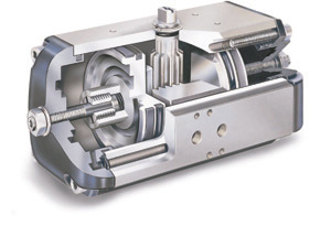
- Pneumatic double acting actuators use gas, typically air or nitrogen to pressurize a double acting cylinder. An unbalance in the opposing cylinder areas drive the connected shaft in the required direction. A 4-way solenoid valve is used to switch pressure between the cylinders. The normal position is the position of the valve with the solenoid de-energized. Available output force is equal to the pressure times the area of the piston (F=PxA). Piston actuators are typically sized for 80 psi minimum. Double acting actuators do not have an inherent fail safe action. If only electrical power is lost, then the valve will go to or remain in its normal position. If pneumatic power is lost, and the friction in the valve and actuator is sufficient to overcome the dynamic unbalance in the valve, then the valve will remain in its last position. If the dynamic unbalance force is greater, then the valve will drift in the dominating direction. Accumulator systems with trip valves are available to provide pneumatic fail safe operation.
- Pneumatic spring return actuators are spring opposed pneumatic cylinders. A 3-way solenoid valve is used to operate a spring return actuator. The normal position is the position of the valve with the spring extended and the solenoid de-energized. The available force is the pressure times the area of the piston less the spring force [F=(PxA)-Fs] in one direction and the available spring compression force in the opposite. Spring force is determined by the spring rate (K) times the compression, in inches (F=KxIn) at any given position of stroke. Spring and piston actuators are typically sized for 80 psi minimum. Spring and diaphragm actuators (for Control Valves) should be sized for 35 psi (6-30 psi signal). Spring return actuators are inherently fail safe. Trip valves are available for lock-in-last position fail action.
- Electric actuatorsuse a reversing electric motor and gear reduction to drive a valve shaft. A given motor size and gearbox are matched to provide the most effective force output. The output force is measured in inch or foot pounds of torque. Standard voltages are 220-480VAC/3-phase, although single phase and 120VAC options are available. Torque switches are used to position the valve open and closed. The normal position is the position of the valve with the solenoid de-energized. Electric actuators inherently fail in the last position. Battery back up is needed to drive the actuator to a specific fail safe position.