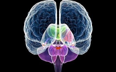
Manual Diaphragm Valves

In twenty-five years, the diaphragm type valve has become one of the industrial standard basic valve types. The valve consists of three simple elements: the valve body, the is illustrated

The diaphragm in this valve serves as the closing, or seat, member as well as the partition that separates the valve working parts (bonnet) from the fluid passageway. The diaphragm is not used as a packing substitute, but instead is used as a dynamic seating element, and eliminates the necessity for the conventional valve stem packing material.

There is some confusion in the engineering profession as regards the meaning of the word diaphragm when referred to valves. An older connotation of a diaphragm has been used by the instrument engineers and manufacturers to denote an outside stem - packed valve, with the stem and throttling element moved by a remote air-motor diaphragm, reacting against a precision spring. (This results in a precise increment of valve stem movement, with relation to air pressure, on the diaphragm motor.) The diaphragm valve to which we refer, and as illustrated, is a valve of truly basic diaphragm design, actually utilizing the diaphragm for closure and separation of the valve working parts from the valve body member.

Tight Closure Feature

The attribute of bubble-tight seat obtainable through the rigid valve weir, and diaphragm seal, creates the principal field of use in those services where drip-tight, bubble-proof closure is mandatory. Today, increased industrial processing costs have come to make this feature paramount, and it is desirable to eliminate wastage of even air and water leakage. All too often, this is thought of as inconsequential. As an example of this, one of the largest automobile assembly plants in the nation is completely equipped with diaphragm valves, in sizes from 1/2 to 12 inch, for air service, at pressures of 100 psi. In this case, initial trials in a prior plant test proved conclusively that the air - escape-free closure saved so much air, normally encountered in accepted leakage, that the valve installation would be rapidly amortized.

In like manner, the valve with this resilient seat feature is very satisfactory in simple water service, particularly where the water may contain grit or suspended material, or be corrosive or scale forming. In this respect, it is even more important that the valve be completely operative after extended service with corrosive and scale-forming water; and without the valve becoming clogged, scaled or cemented shut through long standing. Hence, pitting, corrosion and tuberculation (while not desirable), can be tolerated without the valve becoming inoperative.

Chemical Applications

With the feature of tight shut-off, and with the attributes of a wide selection of construction materials, the valve has accordingly become the industrial standard in chemical process work, where the majority of corrosive processing reagents can be satisfactorily contained within the pressure and temperature limits of the valve. Only reasonable maintenance is required in such cases. These chemical uses have become so widespread that over 700 different process applications have been registered - handling organic and inorganic, corrosive chemical reagents.

The ability of the valve body to be glass, plastic, or soft-rubber-lined - or utilize a host of other construction materials - has permitted it to find application in very severe chemical or abrasive services. Typical are: suspended rouge, alumina, sand, cement, fly ash, lime, gravel and air-blown powders. This can be accomplished by the proper selection and combination of valve body and the particular diaphragm material required for the type of service to be encountered.

Also, the valve has found wide application on such stringent industrial services as vacuum, down to a fraction of a micron, with low leak rates. This has permitted the application of the valve in electronic component manufacturing and pharmaceutical and chemical manufacturing, where the process involves high-vacuum techniques.

A very important example of a difficult application is the wide use of this valve in ion-exchange work for water demineralization. The production of high-ohmic water has resulted in hundreds of installations, utilizing this valve in laboratory and plant demineralizers. For large power plants, particularly, it is important that absolutely no leakage occur in cross-branching, and between resin beds and valve manifolds, so as not to experience regenerant leakage, or demineralized-water contamination.

Diaphragm valves range in size from 1/2 in. to 16 inches; with screwed and flanged-ends available in sizes 1/2 in. to 3 in.; however, flanged-end only in sizes 4 to 16 inch inclusive. The standard elastomeric rubber-base diaphragm operating temperature is from 180°F to 220°F for special heat-resisting diaphragms. The working pressure of the valve is 150 psi in sizes 1/2 to 4 in.; 125 psi in sizes 5 and 6 inch; 100 psi in 8 in. size; 65 psi in 10 and 12 inch; and 50 psi in 14 and 16 inch sizes.

Due to wide variety of diaphragm and body materials required in specific services, any combination of materials with these maximum temperatures and pressures are not always mutually selective. The use of Teflon as a diaphragm material permits the use of the valve at elevated temperatures to 300°F, providing the operating pressure is correspondingly reduced. The type of chemical application at elevated temperature also has a bearing on the maximum permissible pressure, and the valve body construction and type of bonnet assembly best suited for the particular application.

Wide Versatility of Valve

There are several thousand material combinations available, in the broad list of diaphragm and valve body types on the market. For example, in the valve body material the most popular materials are glass-lined, soft-rubber-lined, plastic-lined (many types), hard-rubber lined, cast iron, nodular iron, stainless alloys of different varieties, structural carbon, structural plastic (phenolic, PVC), aluminum bronze, everdur, nickel alloys of many types, polished stainless steel and others.

These valve body materials can be supplied, in most cases, in either screwed-end or flanged-end; also, some types in sanitary-end (polished stainless), brazed-end, or many types of special flanged designs, are available. The diaphragms are obtainable in rubber-base, neoprene, Hycar, Butyl, Teflon, Kel-F, Polyethylene, Teflon-faced and special diaphragm materials on special order.

The basic, three-element design, of body, diaphragm and bonnet assembly, gives wide latitude in the method of operation. Figures 4, 5, 6, 7 and 8 show a few of the many types, such as quick-opening, sliding-stem, cylinder-operated and motor-operated. The valve is very well suited to remote operation, either hydraulic or pneumatic, with pneumatic operation preferred for flexibility and economy.

Thus, the valve can be supplied with either the instrument-type diaphragm motor (with or without a positioner for stem movement precision in throttling service), or equipped with the instrument-type diaphragm motor (or air cylinder) for open - closed service. Extended handwheel, chain handwheel, gear-operated and other designs are produced and made to fit special mounting requirements as industrial valve engineering may indicate. Also, the body of the valve may be equipped with a clean-out port, steam lance, water lance, or drains. A valve which is now standard in the fermentation industry is the antibiotic-type valve, equipped with steam and condensate passages for the continuous maintenance of sterile operation.

Maintenance Features

The diaphragm in its operation, functions both as part of the valve seat, and as a separating member for the operating bonnet assembly; so, there is no need for packing. The absence of packing eliminates the necessity to re-pack the valve; thus the valve is capable of handling fluids without packing leakage.

The three-element construction has the advantage of permitting "inline maintenance", inasmuch as the valve body need not be removed from the line. Instead, removal of the bonnet assembly permits diaphragm replacement and re-assembly of the valve. This reduces maintenance cost involved in line removal; eliminates stem repacking, seat grinding, and the necessity for selective fits that arise in a conventional valve reassembly. The resilient diaphragm member eliminates the necessity for assembly under close tolerance conditions. Usually, as a result of this "in-line maintenance" feature, the only replacement part normally required is the diaphragm.

Adequate care and lubrication of the bonnet assembly parts will insure continued operation. It is seldom necessary to replace any of the operating parts of the bonnet assembly. With the materials available, it is possible to offer maximum corrosion resistance. Selection of the proper body material gives the optimum in corrosion-resistance, and results in long body life, with infrequent body replacement. This type of valve has become so widely used, and the technique of operation so familiar through use, that maintenance is low for those who have become aware of the attributes of the valve.

Referring to Figures 1 and 2, it will be noticed that when the valve is operated from the open to the closed position, the diaphragm movement sweeps out the volume of liquid which must be displaced into the pipe line. This then, is a displacement-type valve and cannot be utilized in so-called locked-lines. A gate valve, for example, is less limited in this respect, in that movement of the valve gate does not displace an equivalent amount of fluid in moving from the open to the closed position. As a result, the ordinary gate valve can be used in a locked-line manifold, and closed as required for operation.

This is not true of a diaphragm valve, inasmuch as inadvertent closure in a locked-line will result in "pumping" of the liquid through positive diaphragm movement, to raise the pressure in the locked line manifold. This can reach the point where the diaphragm will break, or a gasketed surface will leak, until the displaced volume of fluid has been dispelled.

Also, because of the area of diaphragm exposed, and the inherent mechanics of the valve design, the pressure rating is limited. Obviously, pressure acting over the diaphragm surface results in a torque requirement on the valve handwheel which can become excessive. This is particularly true where the valve is used at maximum pressure in a "live-line", where the back-pressure in the valve, during closure, is near maximum. The valve is normally used for free discharge shut-off, or for low back-pressure shut-off; in this case the torque available in one-man operation is adequate. However, where the back-pressure is high, and on large valve sizes, the developed torque from diaphragm pressure reaction necessitates two-man operation. The introduction of a gear and handwheel mechanism permits manual torque-multiplication for valve closure. Obviously, the increased stress on diaphragms at these high pressures results in lessened diaphragm life.

Diaphragm valves are limited in temperature, with most elastomeric diaphragm materials, to a maximum of 180°F. However, specially-compounded, heat-resisting diaphragms are available for continuous operation to 220°F, or short-term operation at 240°F. Solid Teflon diaphragms are available for operation, at reduced pressures, to a maximum temperature of 300°F. Again, with the wide range of materials, together with corrosive-service requirements, and temperature and pressure limits, it is possible that all combinations are not mutually selective.

Shock Resistance

The resiliency of diaphragms frequently assures less damage than would normally occur in a pipe line assembly whee hydraulic shock exists. Unfortunately, and all too often, the hydro-mechanics of industrial lines are either unknown, carelessly planned, or little thought is given to their possible creation and effect. Consequently, the power engineer is ultimately faced with ruptured fittings, broken valves and gages, and secondary effects, resulting from the loosening or vibration of auxiliary equipment in connection with the pipe line.

Conventional valves, incorporating precise seating tolerances, ultimately leak as a result of repeated hydraulic shock or vibration. This is partly overcome through the substitution of the resilient diaphragm. When the magnitude and frequency of hydraulic shock becomes sufficiently great, the diaphragm is incapable of absorbing the standing wave of the shock, and rupture of the diaphragm results. A diaphragm rupture would indicate the hydraulic malfunction existing in the pipe line. Viewed properly, this is not an indication of valve failure, as such, but rather an indication that has pointed up the need for correction of those factors causing improper hydraulic conditions.

One that may increase maintenance on the valve is inadvertent diaphragm overclosure. Psychologically, the valve operator is usually accustomed to metal-to-metal "feel" in closing a valve. Instead, the diaphragm valve gives a cushion closure, and the tendency would be to continue closure until the "feel", or torque resistance, approximates that of a metal-to-metal seat. This is beyond the necessary point for drip, or bubble-tight, closure; and, to prevent such inadvertent overclosure, the valve can be equipped with a tell-tale limit stop. This device gives an indication to all operators when valve is fully closed.

The valve specifications applicable to diaphragm valves are similar to those applicable to other types of standard valves, with one exception. The valve, in some sizes, does not conform to ASA Globe Valve end-to-end dimensions, due to inherent geometry of the design. The valve can be supplied in 125 or 150 psi ASA flange specifications; also, flat-face, raised-face, or in special combinations of valve ends and flange drillings. The material of construction of the valve can be supplied according to ASTM material specifications, where applicable. During assembly and testing, the valve is tested both pneumatically and hydraulically for overall tightness and shut-off. The valve can also meet rigid assembly specifications to pass the G. E. Halogen-Snifter test; also made with special surface finishes, in combination with non-contaminating diaphragm materials, for food, antibiotic and pharmaceutical applications.

The applications of the valve are legion. As an example, nuclear applications have been very satisfactory with the handling of heavy water, solvent extraction processes, and auxiliary services in nuclear chemical plant processing. The valve has found wide application in practically all types of plating processes, inasmuch as it combines ideal corrosion-resistance while avoiding conductance or short-circuiting; also it eliminates contamination of the plating solution.

In the textile industry, the valve has had wide application in synthetic-fiber manufacture, sulphuric and hydrochloric acid handling and manufacture, and nitric acid applications.

Pulp and paper mill applications, tanning, and metal refining applications, are additional uses of valve. To further illustrate the applicability simplified, diagrammatic flow sheet showing typical industrial process where the valves have been given exceptional performance refer to Fig. 9.

Summary

This valve, of all industrial classes, is capable of the greatest selection and combinations of materials of construction. Consequently, the valve has been produced with over 100 combinations of body material, and some twenty combinations of diaphragm materials. Each one of these combinations is dictated by the peculiar requirements of the corrosive solution being handled, and the temperature and pressure of operation.

While not a precision throttling device, the valve has good throttling qualities within limited rangeability, and relatively low pressure-drop characteristics. All of these attributes have further extended its application into the precision control and instrumentation field, for the controlled flow of corrosive and abrasive materials. These rigid requirements have caused this valve to lead the development of new constructional materials, as the demands of corrosion, temperature and pressure have increased.

Resource : R. McFarland Technical Director Hills-McCanna Company Chicago, Ill.