Manual Butterfly Valves
Butterfly valves are one of the oldest practical devices for controlling the flow of fluids. They had their beginnings in light weight, non-tight applications such as dampers. Partly because of this early history of light weight construction, and also because of a lack of adequate flow data, engineers were, for a long time, reluctant to specify butterfly valves in industrial applications. The development of a leak-tight, workable rubber seat, however, gave considerable impetus to the industrial use of the valve, and experience with it soon overcame the early objections.
The first rubber seat butterfly valve was designed by the late William H. Phillips, and manufactured by the Henry Pratt Co. in 1926. This valve found immediate and widespread acceptance in the power industry, the first major industry to make extensive use of it.
As the size of central station equipment increased, with mushrooming power demands, condenser circulating water pipe also increased in size bringing problems in specification of large diameter valving. By specifying the butterfly valve, power engineers secured the advantage of a compact, light weight valve which does not require the use of any supports other than those required by the pipeline itself.
An additional advantage is that natural gum rubber has an excellent "memory", in that it resists permanent indentation. With the natural preservative action of water, the valve seat life greatly exceeds that of any other valve type. One rubber seat butterfly valve, on a test installation, was cycled every 20 minutes for a period of about three years, until a total of 80,000 cycles was accumulated. When returned to the shop, this valve tested bubble-tight.
Function in Power Plants
There are a number of important applications for butterfly valves in modern power plant. One of the main applications is in the condenser backwash systems which provide periodic cleansing of the tube sheets. Some plants employ only partial backwash systems, but the newest have total systems which permit backwashing the condenser without loss of condenser vacuum, and with only a momentary drop in generating capacity. Butterfly valves find their widest power plant usage in these condenser flow-reversing systems.
In connection with reversing systems, we might briefly mention the successful development of the Butterfly Reversing Valve, which can be likened to a giant four-way valve. This valve employs an elliptical butterfly disc to accomplish flow reversal, and is sometimes better suited than are several round valves.
Over the years, dozens of systems have been developed for interlocking, sequencing and actuating butterfly flow-reversing systems. The optimum recommendation can only be made after the valve manufacturer has made a detailed analysis of the hydraulic characteristics of the circulating-water system.
Butterfly valves also find wide use as pump discharge valves, either for sectionalizing service when a number of pumps are connected into a common header, or as emergency closures to prevent flow-reversal in the event a pump goes out of service. Butterfly valves in pump discharge service can be synchronized with pump operation, so they will open as the pump starts; or, the pumps may be set to start operating at any point in the valve opening cycle.
Valves can be installed "fail-safe", so that in the event of pump or power failure, the butterfly valve will close in a specified time. In the case where long lengths of pipeline are involved, a two-speed operator may be required. This type of operator allows the butterfly valve to close, for the major part of its travel, at a fairly fast speed, while the last portion of travel takes place at a considerably reduced speed. This avoids line shock pressures, while minimizing the water lost back to sump. The choice of the two closing speeds, and the exact transition point, is a function of the hydraulics of the system, and should be analyzed by the valve manufacturer for each specific application.
Uses for butterfly valves, other than the aforementioned, are being discovered as power plant technology and design philosophy advance. As an example, with the advent of nuclear power, a new application required the development of the quick-closing butterfly valve. These are used on the air ventilation systems of reactor containment vessels. In normal operation the valves are in the open position, allowing air to circulate through the containment vessel. However, in the event of a reactor incident, these valves must immediately close to maintain safety.
Valve Specifications
Most circulating water valving is designed to a 50 psi standard. Rubber-seat butterfly valves in this pressure class will provide drop-tight shutoff at 50 psi, and will withstand 70 psi shock pressures. This class of valve is suitable for both circulating-water service and most pump discharge application; however, where required, valves in a 125 psi class are available. These valves are drop-tight at 125 psi, and suitable for the most rigorous application.
Since power plant circulating water piping is of fabricated steel, a typical butterfly valve specification would be as follows:
Body Fabricated Steel (ASTM A7)
Disc Fab. Steel (ASTM A7) w/ stainless steel seating edge
Shaft 18-8, Type 304 stainless steel
Bearings Silicone lubricated bronze
Seat Natural Gum Rubber Compound
Taper Pins 18-8 stainless steel
Retaining Segments Nickel Cast Iron
(See Fig. 1 for example.) 
Rubber-seat butterfly valves are manufactured in a wide range of sizes, from 4 inch diameter to 11 feet in diameter, and more. However, these represent extremes in sizing, and power plant valves are usually found in a range from 8 to 60 inches, with a few large plants using valves up to 84 inches in diameter.
Power plants in coastal areas are frequently located close enough to the ocean to use it as a source of cooling water. For these applications, salt water corrosion is a special problem. For the ultimate in corrosion resistance, a valve can be fabricated entirely of monel, but the cost of such construction is quite high, and seldom can be justified. Two suitable and economical alternates are tabulated in the Table.
Alternate No. 1 covers a material specification which has many years of proven service. The bronze and monel material combinations are traditionally the materials chosen for salt water service due to their reliability. Since the keeper segments, and rubber seat, cover the inside surface of the body, the cast iron material specification has proven ideally suited to salt water from the standpoint of corrosion resistance and economy of initial cost.
Alternate No. 2 takes advantage of the newer and more economical materials developed in past years. The Ni-Resist and 18-8 Type 304 stainless steel combinations are being more extensively used as the test of time indicates their reliability.
Selecting the Valve Operator
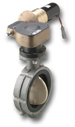
There are three operator types generally used on butterfly valves in power plants. These are: (1) manual gear reducer; (2) electric motor; and (3) hydraulic cylinder. The most popular of these operators is the electric motor (Fig. 2), because its operating requirements are a product of the plant itself. Beyond this obvious fact, however, the push-button control requirements of the modern generating station require an operator which can be remotely controlled, and which is reliable and essentially maintenance-free.
Selecting the Valve Operator
 There are three operator types generally used on butterfly valves in power plants.
These are: (1) manual gear reducer; (2) electric motor; and (3) hydraulic cylinder. The most popular of these operators is the electric motor (Fig. 2), because its operating requirements
are a product of the plant itself. Beyond this obvious fact, however, the push-button control requirements of the modern generating station require an operator which can be remotely controlled,
and which is reliable and essentially maintenance-free. Figure 2
There are three operator types generally used on butterfly valves in power plants.
These are: (1) manual gear reducer; (2) electric motor; and (3) hydraulic cylinder. The most popular of these operators is the electric motor (Fig. 2), because its operating requirements
are a product of the plant itself. Beyond this obvious fact, however, the push-button control requirements of the modern generating station require an operator which can be remotely controlled,
and which is reliable and essentially maintenance-free. Figure 2
The electric motor operator satisfies all of these requirements. The operator consists of an electric motor, coupled through a worm gear assembly which is spline-connected to the valve shaft. Integral limit switches are available for interlocking, sequence operation, and position indication. A torque switch in the motor circuit prevents operator damage, by shutting off the motor if the valve disc meets with an obstruction. Operators may be equipped with remote position indicators and a variety of other equipment to meet specific requirements.
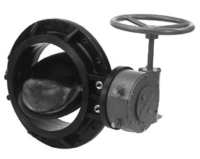 Figure 3
Manual gear-reduction operators (Fig. 3) are used mainly in plants which do not employ automatic backwash systems. Supplied with handwheel or chainwheel, the operator provides great mechanical
advantage, allowing one-man operation of even very large valves.
Hydraulic cylinder operators (Fig. 4) are finding increasing usage in modern power plants. Available in a wide range of sizes, the cylinder operator offers considerable flexibility of selection to meet a particular application. For maximum economy, hydraulic cylinders operating in the range of 1000-2000 psi are usually specified. Where a number of valves are involved, a common hydraulic system may be employed, using a single source of high pressure oil. For single valves, or where their installation is otherwise desirable, self-contained "power packages" are available. These units include the hydraulic cylinder, pump, motor, oil reservoir, and all related valves and controls, mounted together on the butterfly valve.
Figure 4
Hydraulic cylinder operators (Fig. 4) are finding increasing usage in modern power plants. Available in a wide range of sizes, the cylinder operator offers considerable flexibility of selection
to meet a particular application. For maximum economy, hydraulic cylinders operating in the range of 1000-2000 psi are usually specified. Where a number of valves are involved, a common
hydraulic system may be employed, using a single source of high pressure oil. For single valves, or where their installation is otherwise desirable, self-contained "power packages" are
available. These units include the hydraulic cylinder, pump, motor, oil reservoir, and all related valves and controls, mounted together on the butterfly valve
Operator Sizing
A great deal of technical information has been published in recent years, describing the design of butterfly valves. The principal valve manufacturers have printed tables and charts which permit the selection of properly sized operators when flow and pressure conditions are known, eliminating the need for complete evaluation of each application. However, an explanation of some of these design considerations can be extremely helpful in understanding the butterfly valve, in applying it properly, and in specifying it wisely.
The butterfly valve is basically a simple device, but since the configuration of the valve disc (relative to the flowing stream during the opening cycle) is different from other valve
types, the forces encountered will vary. Referring to Fig. 5, we see all of the torques represented, and the relative sequence in which they occur. The torques shown are Th (hydrostatic
unbalance), Ts (seating torque), Tb1 (bearing friction torque, valve closed), Ta (fluidynamic torque) and Tb2 (bearing friction torque under flow conditions).
Figure 5
Hydrostatic unbalance torque, Th, exists only when a large valve, in water service, is mounted in a horizontal pipeline with its shaft horizontal, and the pipeline downstream of the valve is empty, while the upstream pipeline is full. This torque is the result of the hydraulic gradient from top to bottom of the full pipeline, producing an off-center action on the valve disc, with resultant unbalanced torque. The unbalance is given by the formula:
d4
Th = ------
565'
where:
Th = hydrostatic unbalance; lb. inches
d = valve diameter; inches
For the hydrostatic unbalance to be of any concern, the valve must be of large diameter, must open into a dry system, and must be mounted with the shaft horizontal. The likelihood of all three of these conditions occurring at the same time is rare, and the effects of hydrostatic unbalance need not be considered in this discussion.
The seating torque, Ts, as its name implies, is the torque required to rotate the valve disc into, and out of, the rubber seat. Its magnitude depends only on valve diameter and the seat material, and is a constant function for any particular valve design. The bearing friction torque, Tb, is the frictional resistance to rotation imposed on the valve shaft by the bearings. Fig. 5 shows the valve in the closed position where the bearing friction torque, Tb1, is a function of the differential pressure across the valve disc, the disc area, the valve shaft radius, and the coefficient of friction between the valve shaft and bearings. The torque required to open the closed valve, shown in Fig. 5, then becomes the sum of the seating torque, Ts and and the bearing friction torque, Tb1.
As the butterfly valve disc is rotated in the opening direction, a new force is encountered. This is known as the fluidynamic torque, and is shown as Ta in Fig. 5. This torque can be likened to the "lift" experienced by an airplane wing exposed to an airstream. Another good way of describing this phenomenon is the Bernoulli analogy which states, very generally, that a region of low velocity is a region of high pressure and, conversely, a region of high velocity is a region of low pressure. Referring to Fig. 5, it is seen that the trailing edge of the disc forms a nozzle-lie configuration with the valve body, whereas the leading edge forms a rather orifice-like configuration with the valve body.
Logic dictates that the trailing edge opening would become the region of high velocity, and the leading edge opening one of low velocity. The resultant pressure distribution pattern, in Fig. 5, shows a pronounced unbalance on one side of the valve shaft which, when summed up about the centerline of the valve shaft, results in the fluidynamic torque, Ta, tending to close the valve. Reversing the flow through the valve will still create a fluidynamic torque acting to close it, since the positions of the leading edge and trailing edge have simply been reversed, and the resulting pressure distribution is unbalanced in the same way.
The magnitude of the fluidynamic torque is dependent on a mathematical relationship between the valve diameter, flow velocity, angle of the valve disc, and pressure distribution across the valve. Its peak usually occurs between disc angles of 30 and 80 degrees. Equations developed from experimental flow data enable the prediction of this torque quite accurately. The bearing friction torque, Tb2, is distinguished from the torque, Tb1, because it varies throughout the opening cycle of the valve as the pressure drop varies with valve disc angle.
Fluidynamic torque, Ta, and the bearing friction torque, Tb2, are additive for the opening of the valve. As the valve is being closed, however, the bearing friction torque, Tb2, subtracts from Ta, since the bearing friction torque reverses algebraic sign as the direction of shaft is reversed.
Once all of these torque values have been established, the operator sizing becomes a relatively simple matter. The fluidynamic torque, plus bearing friction torque (open), (Ta + Tb2), are calculated for various valve angles, and the peak value determined. This peak value is then compared with the seating torque, plus bearing friction torque (closed), (Ta + Tb1). The larger of the values of (Ta + Tb2 or (Ts + Tb1) governs the choice of operator size.
Flow Characteristics of Valve
 Butterfly valves, in addition to serving as shutoffs, can also be used for throttling applications. An index of the excellent throttling characteristics of the butterfly valve is the fact
that it has a control rangeability of 45 to 1. A rubber-seat butterfly valve can be used for throttling service and, when required, can be moved to the full closed position to give tight
shutoff.
Butterfly valves, in addition to serving as shutoffs, can also be used for throttling applications. An index of the excellent throttling characteristics of the butterfly valve is the fact
that it has a control rangeability of 45 to 1. A rubber-seat butterfly valve can be used for throttling service and, when required, can be moved to the full closed position to give tight
shutoff.
In Fig. 6 there is a tabulation of the flow coefficients, Cf, and corresponding head loss K-factors, for valve angles from full closed to full open position. The left column cover flow coefficients and head loss factors for a 50 psi design valve, while the right columns cover the 125 psi construction. The heavier disc construction of the 125 psi valve reflects itself in the higher head loss coefficients, for valve angles 80 to 90 degrees.
Figure 6
It is interesting to note that up through the angle of 75 degrees, the loss coefficients for both the low-pressure and high-pressure construction are identical. This results from the fact that up to this point the head loss coefficient is a function of the valve disc angle only. From about 75 degrees, to the full open position, the disc thickness becomes the controlling factor, as the leading edge of the disc begins to swing into the "shadow" of the disc thickness. Since the high-pressure valve disc is thicker than the low pressure disc, the corresponding head loss factors in this range are higher. In addition to these coefficients, Fig. 6 has various formulas for flow, velocity, and head loss for use with the coefficients.
Summary
This brief outline indicates the scope of butterfly valve equipment, operators, controls and control arrangements that are available for power plant use. In order to obtain equipment recommendations which will yield optimum results in service, it is advisable to contact one of the number of reputable valve manufacturers in this field. Using the wealth of technical data validated by years of practical experience, the valve manufacturer can solve valving problems, provided he has a thorough knowledge of the application involved. The valve manufacturer can supply the experience, but information about the application can come only from the power engineer.